HP-05: Replacing the lights in a cheap stereo
Preface #
This post is the fifth installment of my “Hobby Programming” series. I have two other projects that have been in the works since I published the last installment, but they are both a fairly large step up in difficulty. While I am still hard at work on those projects, it will still be a bit before I can write a full article about them. While this project is pretty short and not programming related, I felt it still may be interesting to some people.
Introduction #
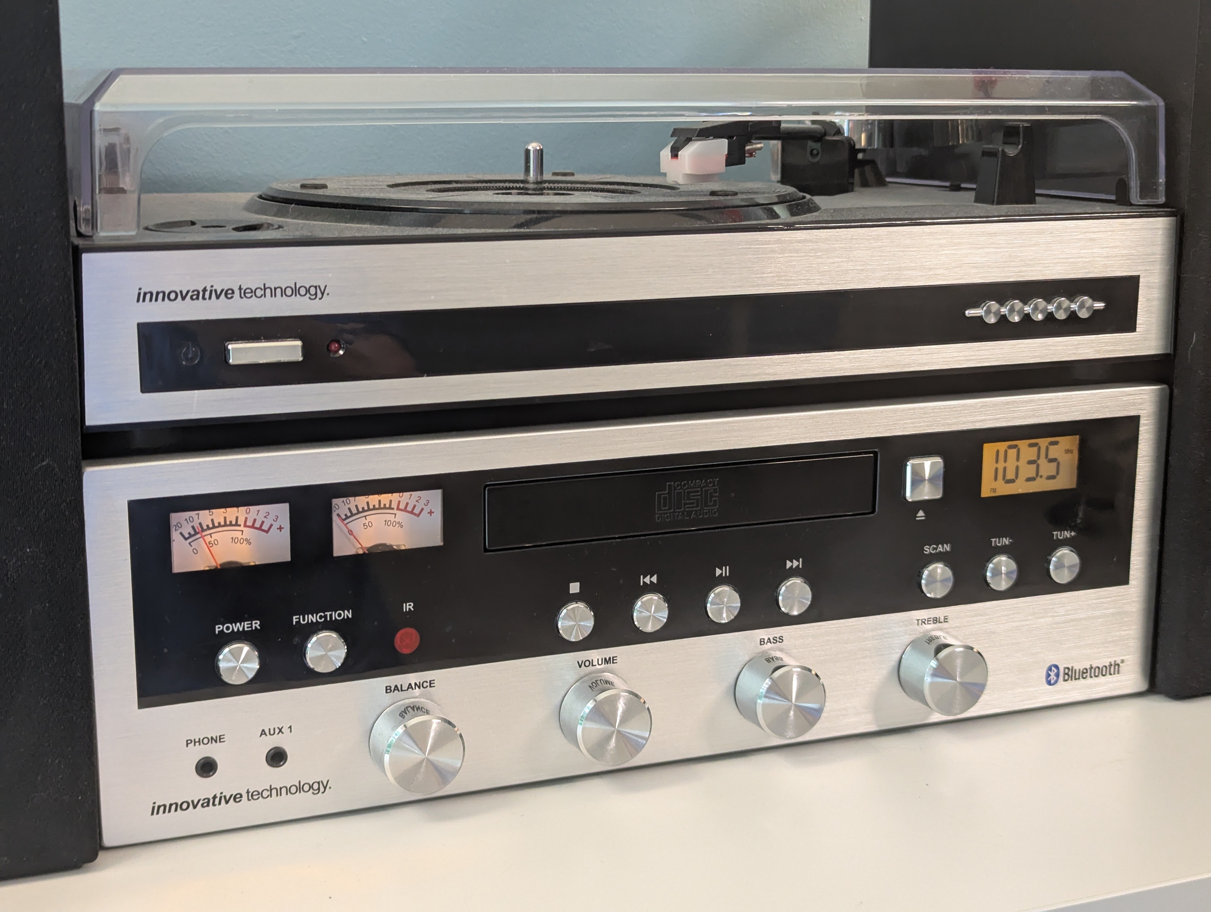
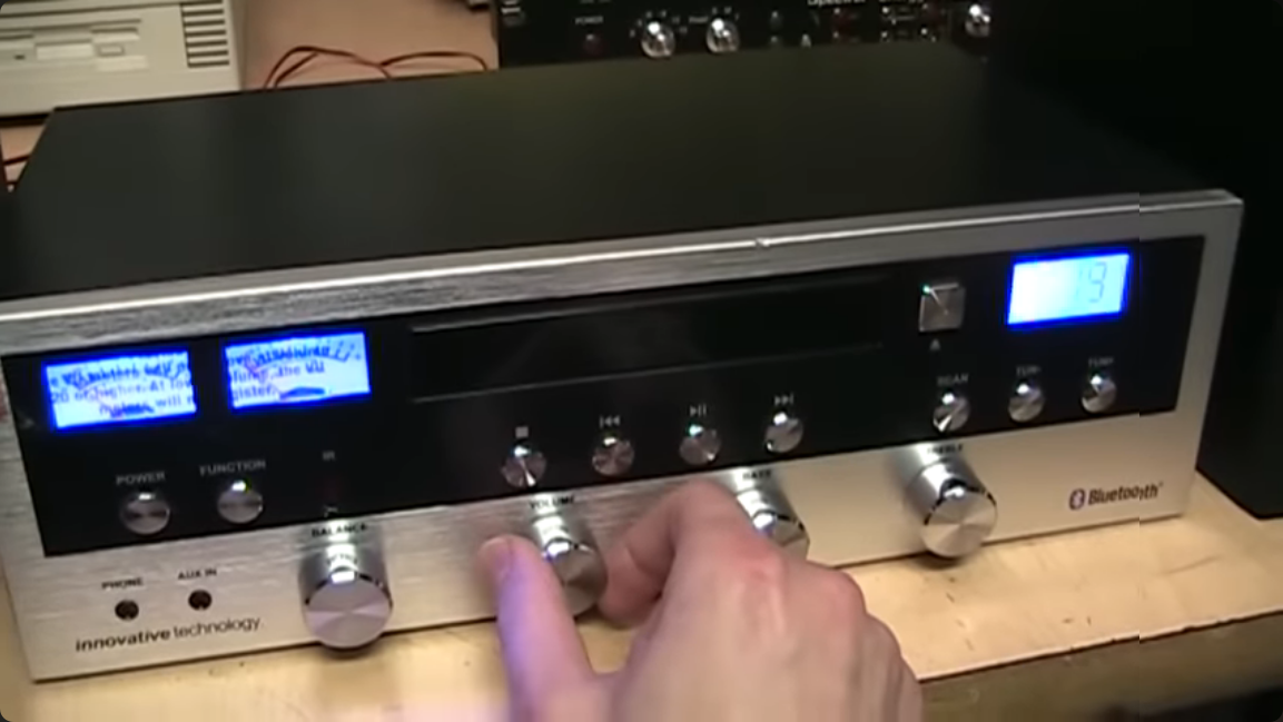
I have had an ITCDS-5000 stereo system for a long while now. It’s not anything exceedingly stellar, but it’s perfectly serviceable for playing the radio or other media via Bluetooth. If you want a more in-depth review of the unit, this VWestlife video covers it well. My model did come with the record player option, and it’s worth noting that my model looks fairly different internally than his unit, with some more boards and a bit less cable management. However, I have always disliked the blue LEDs that backlight the VU meters and the LCD screen. They are far too bright and I have felt that the color is fairly harsh on the eyes. In order to finally rectify this issue, I decided to open it up and see if I could swap them out for another color, hopefully something dimmer and more relaxing.
Opening it up #
The system is easy enough to open up, with 9 screws holding it’s metal case attached. With the case removed, we get a good look inside of the device. There are a surprising number of PCBs, ribbon cables, and flat-flex cables going all throughout the device. Luckily, the lights for the VU meters are fairly easy to access. They live on a little board with two little soldered wires for positive and negative. The board comes out with two screws, and the wires were just long enough to hold the board on top of the case. They used two little rectangular blue LEDs, one for each meter. Luckily, in my stash of LEDs I found some 3mm round yellow LEDs that would give a nice warm glow.
I had started by replacing one of the LEDs to make sure that it worked as I hoped, but my new LED instantly burned up! I knew that I may have needed to add a current limiting resistor, but luckily since this board was so simple that would be a fairly easy task. After measuring the voltage that the stereo provided I decided to use a 100 ohm resistor in series with each LED.
3.7V ÷ 100 Ohms = 37mA
I tested these parameters with an adjustable power supply, and the light lit at a nice brightness.
I didn’t desolder the wires that connect the board because they were also coated in some kind of glue that I would rather just not remove. In fact, there was all kinds of hot glue and other glue thought the inside of the device. On many wires in the stereo there were long strands of hot glue.
I sliced through the positive traces on the board that went to each LED and I sanded off small pads in the solder resist on the traces. I using these, I soldered a 100 ohm resistor in series with each LED. I bent the LED’s down so that pointed into the diffraction grating that spreads the light over the meter and the effect was very good. The harsh blue light was finally replaced by a nice warm glow.
Onto the LCD #
The next step was to replace the backlight on the LCD screen. This seemed like it was going to be more of a challenge. The entirety of the front panel, save for the VU meters and their backlights, were one large PCB that stretches the full length of the machine. It seemed like it would be a challenge to take the whole board out. By examining the back of the board I was able to identify the familiar pattern of a LCD screen on the back and it appeared that the backlight might just be a single LED on the outer edge of the PCB. That was the best case scenario, because I would only need access to the very edge of the board.
First, I needed to find a way to separate the front panel from the rest of the machine. I started by removing two screws from the sides of the front panel. There were another two screws that held the panel down to the base of the machine. With those removed, the front panel still wouldn’t budge. I figured out that the CD player was still holding it in place. By removing four screws, two from the front of the mechanism and two from the back, I was finally able to lift up the front panel and rotate it vertical.
Luckily the side of the board I needed to access was on top, perfect! However, there were still many screws holding it to the front panel, but by removing screws from the side with the display I was able to bend the thin PCB far enough away from the front panel to get access to the LED. To avoid burning out another LED, I inspected the board to check if it had a current limiting resistor. Luckily it did have a small 100 ohm surface mount resistor. This was great because this board was much more dense than the other board, and it could have been a bit challenging to add a resistor.
I desoldered the blue LED, which turned out to be the same as the other ones and replaced it with a yellow one. I plugged it in to make sure the LED wouldn’t burn out, and they all looked great. I reassembled the whole thing and put it back into it’s position. I think that the new backlights are a huge improvement to the set and really help look a lot better.